Capture The Flag Challenge
Learning Objectives
The learning objectives for this challenge are to:
Understand UDS / ISO-TP diagnostics
Use can-utils to query an ECU
Inspect firmware to find embedded data
Overview of Challenge
Unified Diagnostic Services (UDS) is a communication protocol that is primarily used in the automotive industry for diagnostics and testing. It runs on top of CAN FD and provides a common set of diagnostic functions like ECU programming and data monitoring. UDS enables ECUs to interact constantly across different vehicle manufacturers and systems.
UDS exploitation refers to cyberattacks that target the diagnostic services in a vehicle. Attackers with access to the CAN FD bus can use UDS commands to read data or overwrite ECU memory. The RAMN device is used to simulate and practice UDS attacks. The type of attack used in this challenge is Service Identifier (SID) exploitation.
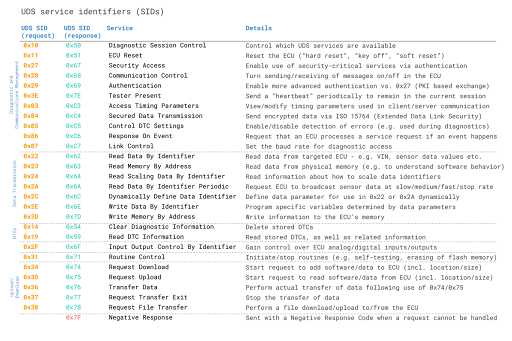
When an attacker (you in this case) wants to utilize a specific service, the UDS request message should contain the UDS Service Identifier (SID) in the data payload [2]. SIDs are required in the UDS request message to utilize a specific UDS service.
This is most easily done on a Linux system; you may use a virtual or local machine with can-utils installed. We will be using the commands from section 2.0, specifically sending UDS commands to retrieve the flag.
Challenge Part 1
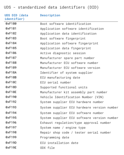
Retrieve the hidden message embedded in the ECU firmware and submit the flag. The format of the flag is: “RAMN FLAG {‘flag’}. Attached below is a list of UDS SID service requests and responses. Also included is a list of data identifiers. Use a Linux terminal to retrieve the flag. See the “Installing Linux”, “UDS Background Information”, and “Viewing CAN” sections to get started with the project. Shown below are tables for the UDS Service Identifiers and UDS Data Identifiers. Do not disable any of the ECUs.
Environment:
Linux
CAN interface
Can-utils
Challenge Part 2
Background:
Extended Linear Address (ELA) records contain the upper 16 bits of a data address. The format of an ELA record is: 02000004FFFFFC Where:
02 is the number of data bytes in the record
0000 is the address field (always 0000 for an ELA record)
04 is the record type
FFFF is the upper 16 bits of the address
FC is the checksum of the record
An Intel HEX data record is formatted like: : LL AAAA TT [Data…] CC, where
LL indicates the byte count
AAAA indicates the 16-bit offset
TT indicates the record type
CC is the checksum
When an ELA is read, the ELA address stored in the data field is saved and is applied to subsequent records read from the Intel HEX file [1]. The absolute memory address of a data record is obtained by adding the address field in the record to the shifted address data from the ELA record [1].
The ELA used in this project is 020000040801F1.
Challenge:
Somewhere in the flash is a printable flag with the format FLAG{…}. Use the ST-Link debugger, the debug board, and the STM32Cube Programmer to identify the memory location of the flag. The flag is stored on ECU B in the ECU’s .hex file. Find the flag in the .hex file and submit the flash address where the flag begins. Submit the flag in the format 0x0801XXXX.