Capture The Flag Challenge Solutions
Part 1
Two terminals are required to identify the flag. The spare part DID (Data Identifier) is 0xF187. The first step is to send a UDS ReadDataByIdentifier request (0x22) for DID 0xF187. The request bytes are ‘22 F1 87’. The command ‘isotpsend -s 7e1 -d 7e9 slcan0’ sends the ISO-TP message from CAN ID 0x7E1 to 0x7E9. The ECU then responds with an ISO-TP message containing a positive response to 0x22. The UDS SID response to 0x22 is 0x62. The DID echo follows ‘F1 87’, so the header in the reply is ‘62 F1 87’. The payload bytes with the response follow the header in Terminal 2. The bytes that follow the reply after the UDS header in Terminal 2 are the ASCII characters of ‘RAMN FLAG{lets_go_hokies}’.
- Terminal 1:
echo “22 F1 87” | isotpsend -s 7e1 -d 7e9 slcan0
- Terminal 2:
kali㉿kali)-[~]
└─$ isotprecv -s 7e1 -d 7e9 -l slcan0
62 F1 87 52 41 4D 4E 20 46 4C 41 47 7B 6C 65 74 73 5F 67 6F 5F 68 6F 6B 69 65 73 7D
Part 2
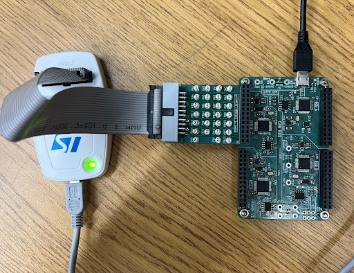
Connect the ST-Link and debug board to ECU B, with the connector facing away from the middle of the board. Note: The RAMN board must be connected to power when using the debugger. See ‘Using STM32Cube Programmer’ under “Firmware Flashing” for information on how to connect the board to the board to the debugger firmware.
After the board is successfully connected to the STM32Cube Programmer, the debugger will display the information below.
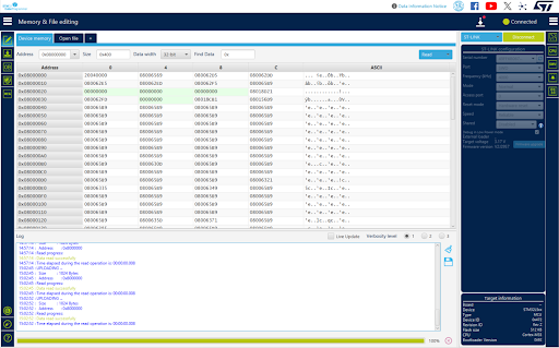
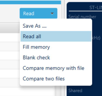
From the ‘Memory & File editing’ tab, select the ‘Read’ dropdown in the top right corner. Select ‘Read all’ and wait for the debugger to read all of the memory addresses.
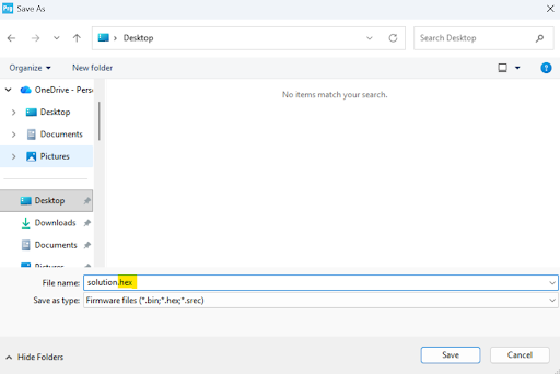
After reading all of the flash memory, save the data using ‘Save As …’ and make the file extension a .hex file.
We know that the flag is ‘lets_go_hokies’, so we need to convert part of the flag from ASCII to hex characters. The section our group used to find the address was ‘lets_go’, which is ‘6C 65 74 73 5F 67 6F’ in hex. Open the .hex file in a text editor, like Notepad, and search for ‘6C6574735F676F’ in the file. The line that contains the beginning of the flag is the address of the flag in flash memory.
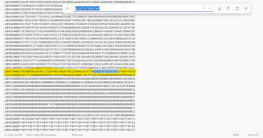
The first six values of the line with the flag are ‘209C40’. From the review above, we know that the first two values, 0x20, mean that 32 bytes follow, and the next four values, 0x9C40, are the 16-bit offset for the data. Also from above, we know that the Extended Linear Address is ‘020000040801F1’, which means that the payload is ‘0x0801’. This means that the upper 16 bits of the memory address are 0x08010000. The absolute address is the sum of the ELA upper 16 bits and the 16-bit offset, which is ‘08010000 + 9C40’, so the start address of the line with the flag is 0x08019C40. Enter this line into the address bar of STM32Cube Programmer, and you will see that the flag begins on line 0x08019C50.
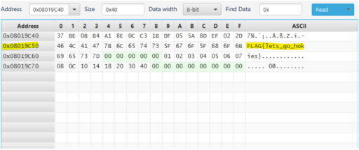
This occurs because the full line of data is ‘37 BE 0B B4 A1 8E 0C C3 1B DF 05 5A 8D EF 02 2D 46 4C 41 47 7B 6C 65 74 73 5F 67 6F 5F 68 6F 6B 2B’. Each pair of hex digits is equivalent to one byte. As shown above, there are 16 bytes before the first line of the flag begins, which means that the flag starts 16 bytes into the data field. Therefore, there is an offset of 0x10. Add the 0x10 offset to the memory address of the start of the line, and the flash memory address is 0x08019C50.